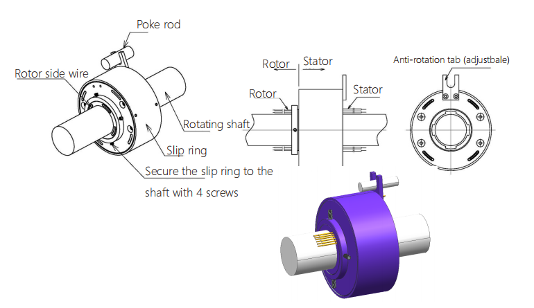
LPT000-0410-0602-24S-01E3 Outline Drawing
Electronic & Electric |
Mechanical | |||
Circuits |
18* 2A + 16* 10A + Gigabit Ethernet |
Working Speed |
0~300rpm |
|
Inner Diameter |
∅180mm |
|||
Rating Voltage |
24VAC/VDC |
Contact Material |
Gold to Gold(S) Precious Metal |
|
Dielectric Strength |
500VAC@50Hz(P) 100VAC@50Hz(S) |
Shell Material |
Aluminum alloy |
|
Insulation Resistance |
≥500MΩ@500VDC(P) ≥100MΩ@250VDC(S) |
Contact resistance fluctuation value |
≤70mΩ |
|
Environment |
Remarks | |||
Working Temperature |
-40°C~+80°C |
Application |
/ |
|
Working Humidity |
≤70%RH |
Other |
/ |
|
IP |
IP65 |
Note: "P" stands for power, "S" stands for signal. |
||
LPT Through-bore Slip Rings Installation Guide:
1.Arrange wires of the rotor side and the stator side before installation. Stabilize the slip ring on the rotating shaft. Adjust the position of the shaft and the mounting hole and use 4 screws on the rotor side to fasten the components. Ensure the concentricity between the shaft and the slip ring before fixing the screws.
2.Insert the poke rod in the U slot of the anti-rotation tab. Meanwhile, arrange the wires to avoid twining with the rotor.
3.Slip rings are precise electronic components. Take protection measures in case of harsh environment or apply slip rings with higher protection level.

LPT Through-bore Slip Rings Precautions:
1.The slip ring cannot bear the weight of its connected equipment. Also, wires should be free from extra pull and weight.
2.Keep wires intact during installation to avoid any poor performances due to damage of the wire insulating layers.
3.Adopt flexible connection instead of rigid connection between the rotor side and the stator side to ensure longer life span of the slip ring.
4.Stabilize the screws with locking measures to avoid loosening and dropping due to vibrations and shocks during operation