
LPT012B-0302-U2 slip ring has become the first choice in many high-end applications due to its excellent signal transmission capability and high reliability. Whether you need industrial automation solutions, robotic system support, or other high-precision signal transmission needs, LPT can provide you with ideal products and services.
Contact us to learn more about the LPT012B-0302-U2 slip ring details and customized services, provide high-performance signal transmission solutions for your equipment, and help you innovate technology and improve production efficiency!

Through Bore slip rings are also called hollow shaft slip rings. Their through bore design is designed to facilitate installation on the shaft at the application end, allowing other fluid/gas channels or power lines to pass through. They can be flexibly installed on the shaft of the robot arm to help manipulate and connect to different joints of the application; they can transmit analog signals, digital signals and electricity, and are widely used in industrial manufacturing. In addition to allowing pipes and wires to pass through the slip ring unit, the hollow shaft structure can also be integrated with other electrical slip rings, such as RF slip rings, fiber optic rotary joints, and hydraulic and pneumatic rotary joints.
LPT012B-0302-U2 Outline Drawing
Electronic & Electric |
Mechanical | |||
Circuits |
3* 2A + 4 *signal |
Working Speed |
0~300rpm |
|
Inner Diameter |
∅12.7mm |
|||
Rating Voltage |
380VAC |
Contact Material |
Precious Metal |
|
Dielectric Strength |
1000VAC@50Hz(P) ≥100VAC@50Hz(S) |
Shell Material |
Aluminum alloy |
|
Insulation Resistance |
≥500MΩ@500VDC(P) 100MΩ@100VDC(S) |
Lead Wire Length |
Stator:3* 2A:180mm USB2.0:150mm Rotor:3* 2A:420mm USB2.0:370mm |
|
Environment |
Remarks | |||
Working Temperature |
-20°C~+60°C |
Application |
/ |
|
Working Humidity |
≤60%RH |
Other |
/ |
|
IP |
IP54 |
Note: "P" stands for power, "S" stands for signal. |
||
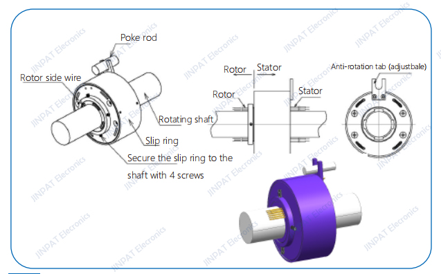
LPT Through-bore Slip Rings Installation Guide:
1.Arrange wires of the rotor side and the stator side before installation. Stabilize the slip ring on the rotating shaft. Adjust the position of the shaft and the mounting hole and use 4 screws on the rotor side to fasten the components. Ensure the concentricity between the shaft and the slip ring before fixing the screws.
2.Insert the poke rod in the U slot of the anti-rotation tab. Meanwhile, arrange the wires to avoid twining with the rotor.
3.Slip rings are precise electronic components. Take protection measures in case of harsh environment or apply slip rings with higher protection level.
LPT Through-bore Slip Rings Precautions:
1.The slip ring cannot bear the weight of its connected equipment. Also, wires should be free from extra pull and weight.
2.Keep wires intact during installation to avoid any poor performances due to damage of the wire insulating layers.
3.Adopt flexible connection instead of rigid connection between the rotor side and the stator side to ensure longer life span of the slip ring.
4.Stabilize the screws with locking measures to avoid loosening and dropping due to vibrations and shocks during operation